Vodárny V1 - V4/en
| Main page | Laboratory models | Courses | Equipment | History | Administrator | For students | Links | |
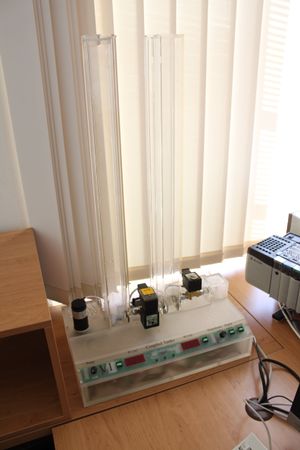
Laboratory models Coupled tanks V1 - V4 were made in Jiří Hanzlík's diploma thesis [1] in 2008 as models of controlling water level in coupled tanks with closed loop. They are used for education regulation and simulation of dynamic systems and likewise programmable controllers (PLC). They simulate systems in petrochemical, chemical or another industry or water-resources management. Photogallery of industry application to models in Lab. K26 website
Description of the model
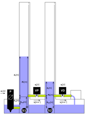
The model contains the centrifugal pump, two tanks, two valves and the reservoir of water. Also it's featured by the control panel which provides a manual control. Also displays values of water level in tanks and provides the signalization of controlling by Matlab with Real-Time toolbox or programmable controller (PLC).
Water is pumped from reservoir into the first (left) tank. Next water streams through first valve into the second (right) tank. Behind the right tank is the escape valve to the reservoir of water. The pump is behaved as a one way flow source. The input value is input voltage of the pump u. For measurement water levels h1 and h2 are used pressure sensors which transform physical values to electric signals. For using Matlab/Simulink are converted to non-dimensional signals in range <0, 1>.
Information for students
General information [2]
- The system is nonlinear and stabile.
- All four models have same dimensions and are equipped with identical components,
but their dynamic is changed on purpose.
- Valves configuration: models V1 a V2 have
the middle valve proportional and the escape valve digital. In V3 and V4 it is conversely.
- For basic regulation (SAM/SRI courses) are both valves within identification and regulation
fully open.
- Models is possible to control with:
- Programmable logic controller (PLC)
- Matlab
- Manual
- The sequence implicate the priority order of controlling, i.e. the lowest priority to manual control.
If the control is activated with a higher priority, it automatically assumes control of the model.
Instructions
- To start the pump without water is prohibited - danger of destruction!
- Beware of overflow tanks - spillovers can be overload.
- After the end of working with Simulink model the pump should be stopped and model should be switched off.
Inputs
- gear pump voltage u1 [V] - actuating value
- rate of opening proportional valve u2 [V]
- opening/closing of digital valve u3 [V]
Outputs
- water level in the first (left) tank h1 [m]
- water level in the second (right) tank h2 [m] - regulating value
Useful formulae
Relation between the velocity of fluid v [m s-1] and its high h [m] is
<math>v(t)=\sqrt{2 \, g \, h(t)}~\text{.}</math>
Relation of pressure p [Pa] from the centrifugal pump and its voltage u [V] is quadratic
<math>p(t)=k \, u^2(t)~\text{.}</math>
References
- ↑ HANZLÍK, Jiří. Distribuovaný řídicí systém s automaty Rockwell Automation. Praha, 2008. xvi, 56 s. Diplomová práce. ČVUT-FEL, Katedra řídicí techniky. Vedoucí práce Ing. Jindřich Fuka.
- ↑ KONOPA, Miroslav. Řízení výukových modelů typu Spojené nádoby. Praha, 2009. vii, 40 s. Bakalářská práce. ČVUT-FEL, Katedra řídicí techniky. Vedoucí práce Ing. Jindřich Fuka.

