Control moment gyroscope by ECP
Skočit na navigaci
Skočit na vyhledávání
Educational four-axis control moment gyroscope - Model 750 from Educational Control Products (ECP).
Link to the product web page on the producer's site
Located currently at K26 lab.
Troubles:
- the system is provided with the so-called turnkey solution, which means that besides the model itself, an amplifier and also the software was delivered.
Student projects finished with the system:
MATLAB® Controll using Real-Time Windows Target® and Humusoft Control Board
Individual Project
Krištof Pučejdl
Motivation:
- Dedicated control software provided by ECP is very outdated. It requires old 32 bit processor architecture and the user interface does not match today's standards.
- Most of the control models being used in education are controlled via MATLAB® using universal Humusoft® control board. Using the same board to control different models is way more flexible and allows switching the controll PC's without need of hardware changes.
Goals:
- Find the correct setup of Humusoft® board according to pin-out specification provided by ECP.
- Set up and run the RTWT® communication in MATLAB®
- Describe the input values to actuators and output values from sensors.
- Experiment with regulators and feedback control.
1. Model Description
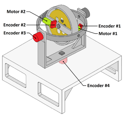
- ECP's four axis Control Moment Gyroscope consoist of revolving intertia disc mounted in three axis gimbal. Inertia disc rotation axis (#1) and the first (inner) gimbal axis (#2) are driven by servo motors (Motor #1, Motor #2), while the movement along each axis is measured by incremental sensors (Encoder #1-#4). Range of motion along the second axis is limmited by end-stop switches to about 300*. The other axis allows unlimmited rotation.
- Positions of Encoders and Moters are displayed on Figure 1.

- Axis #3 and #4 are equipped with electromechanical breaks that are either operated manually via switches on Ampflier box or swiched on automatically by end-stop or inetria switches.
2. Humusoft board setup
- Gyroscope Ampflier/Interface box uses 60-pin Flat Cable for connetnion with original ECP control board. 14 pins are used to provide power supply and data acces to four encoders (Encoder 1-4) and two Digital-to-analog converters that drive motors (DAC 1-2). All devices are described in previous section.
- Each Encoder requires 4 wires. Two for TTL Signal data on Channel A and B, one for power supply (+5 Volts) and one for ground. Power supply and ground are common for all four encoders.
- Each Motor requires 2 wires. One for input DAC Signal (input range +/-10 Volts) and one for ground.
- The original pin-out specification provided by ECP (on request) contained several errors. Following specification table is already corrected.
| Signal Description | Pin Number | Very Important Notes |
|---|---|---|
| Encoder 1 A Channel | 25 | TTL Signal |
| Encoder 1 B Channel | 21 | TTL Signal |
| Encoder 1 +5 V Power Supply | 1 | DO NOT MIX UP +5 Volt & Ground. Causes immediate damage to encoders. |
| Encoder 1 Ground | 3 | Encoder Power Common |
| Encoder 2 A Channel | 26 | TTL Signal |
| Encoder 2 B Channel | 22 | TTL Signal |
| Encoder 2 +5 V Power Supply | 1 | DO NOT MIX UP +5 Volt & Ground. Causes immediate damage to encoders. |
| Encoder 2 Ground | 3 | Encoder Power Common |
| Encoder 3 A Channel | 13 | TTL Signal |
| Encoder 3 B Channel | 9 | TTL Signal |
| Encoder 3 +5 V Power Supply | 1 | DO NOT MIX UP +5 Volt & Ground. Causes immediate damage to encoders. |
| Encoder 3 Ground | 3 | Encoder Power Common |
| Encoder 4 A Channel | 14 | TTL Signal |
| Encoder 4 B Channel | 10 | TTL Signal |
| Encoder 4 +5 V Power Supply | 1 | DO NOT MIX UP +5 Volt & Ground. Causes immediate damage to encoders. |
| Encoder 4 Ground | 3 | Encoder Power Common |
| DAC 1 Spin Motor | 43 | MAX +/- 10 Volts |
| DAC 1 Return | 58 | DAC 1 Common |
| DAC 2 Gimbal 2 Motor | 44 | MAX +/- 10 Volts |
| DAC 2 Return | 58 | DAC 2 Common |
This specification is used for setting up propper connection with Humusoft® board using two universal terminal boards (Humusoft® TB620).